
Inertial Sensors
Sensors to detect motion in three dimensions
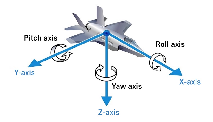
Vehicles moving in three dimensions, like aircraft and submersibles, need to know their own attitude, speed and position. Used for this purpose are inertial measurement units (IMUs), that are sensors to detect angular rates around roll, pitch and yaw axes and acceleration rates in the directions of X, Y and Z-axes.
An IMU measures its own angular and acceleration rates with embedded gyroscope sensors and acceleration sensors, three each corresponding to the coordinate axes of the vehicle (see the figure on the right.) From this measurement data, onboard computers work out attitude, heading, speed and position in real time; the vehicle's speed and position can be determined by transforming acceleration of each axis to coordinates with attitude and heading calculated from angular rate of each axis, then integrating it. Such means of navigation is called the strap down method. An IMU measures its own angular and acceleration rates with embedded gyroscope sensors and acceleration sensors, three each corresponding to the coordinate axes of the vehicle (see the figure above.) From this measurement data, onboard computers work out attitude, heading, speed and position in real time; the vehicle's speed and position can be determined by transforming acceleration of each axis to coordinates with attitude and heading calculated from angular rate of each axis, then integrating it. Such means of navigation is called the strap down method.
On aircraft, calculated navigation data is generally sent to autopilot systems and used for navigation to the destination, as well as shown on cockpit displays.
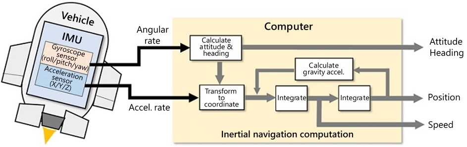
Strap down inertial navigation
Optical gyroscopes are capable of measuring angular rates smaller than that of the earth's rotation (15°/hour approximately.) Particularly FOGs cover a wide range of performance.
Inertial navigation of aircraft, that needs highly precise measurement, requires a gyroscope sensor's output to have a bias stability higher than that of the earth's revolution (0.04°/hour approximately) and high stability of the scale factor.
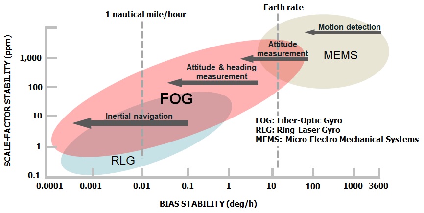
Accuracies and suitable applications of three types of gyroscope sensors:
The smaller in the vertical/horizontal axis, the higher scale factor stability/bias stability is.
FOG
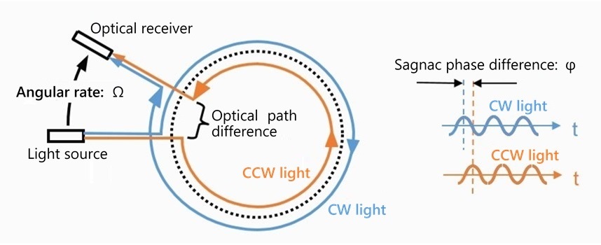
Principle of FOG (Sagnac effect)
A fiber optic gyroscope (FOG), which applies a principle based on the theory of relativity called Sagnac effect, measures angular rate around the axis of its optical fiber coil by detecting the phase difference between two lights, one traveling in the coil clockwise and the other counterclockwise.
The formula below shows the relation of angular rates (Ω) and resulting Sagnac phase differences (φ.)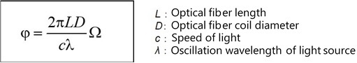
FOGs also have advantages such as no disturbance, high reliability and long life, since they are completely motionless gyroscopes having no movable parts.
Such features set the FOG apart from other types of gyroscopes, enabling it to be used in a wide variety of applications including aircraft, ships, submersibles, cars and other vehicles, civil engineering and construction.
An FOG is composed mainly of the optical system for detecting angular rate and the circuit for processing signals. With our technology to precisely make optical fiber coils and application of our unique digital closed-loop singal processing method, we realized high precision FOGs capable of measurement up to ±1000°/sec in addition to high bias stability and scale factor linearity.
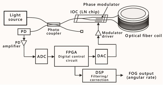 FOG block diagram
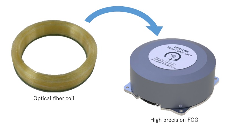
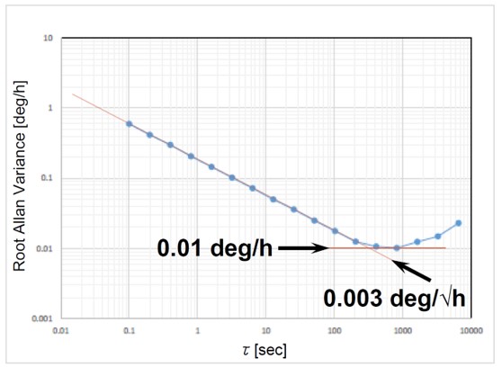
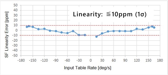
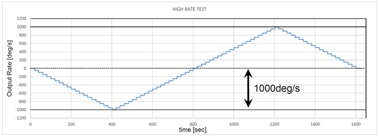
FOG performance evaluation samples
(Allan variance, scale factor linearity & measurement range evaluations)
Click to enlarge image.
Application to inertial navigation systems
In addition to expertise in gyroscope and acceleration sensors, we have acquired technology of software-based attitude and navigation computation. We have produced an INS/GNSS; an inertial navigation system that corrects its inertial sensors' measurement data by comparing it to positioning data from the global navigation satellite system (GNSS) and obtains highly accurate navigation data.Attitude and navigation computation in strap down method, if using measurement data from inertial sensors uncorrected, has a tendency that errors in calculation results gradually grow by integrating each sensor's datum containing an error.
The INS/GNSS executes compound navigation operation, which estimates errors in each sensor's outputs and each physical quantity by comparing the GNSS positioning results (that are discontinuous and containing errors but distributed around the true value) with navigation computation results (that uses continuous inertial sensors data) and works out the most probable values. It can obtain optimized navigation data without growing errors in any of attitude & heading, speed or position, by exploiting the advantages of both the inertial sensors and the GNSS using an error estimation algorithm called Kalman filter.
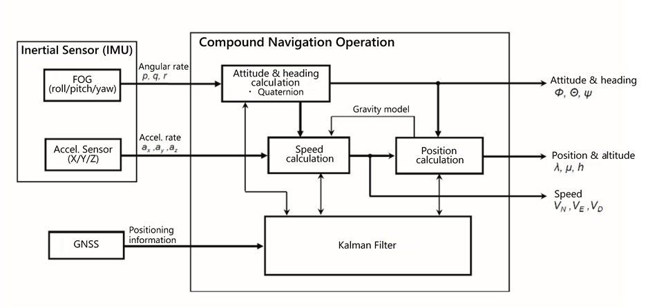
INS/GNSS block diagram
Concept of the INS/GNSS, fusing inertial navigation and GNSS positioning
In years of studying the strap down inertial navigation system, TKK has developed related element technologies in-house, from hardware including inertial sensors and electric circuits to navigation computation software. The system's operation and performance were validated by extensive field tests on aircraft and cars to meet actual use environments.
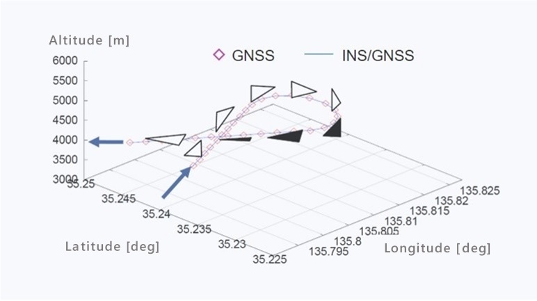
For evaluation, we installed it along with MSAS-GAIA, a next-generation ultra-precision inertial navigation system using ring laser gyroscopes, on a testbed airplane Mupal-α of the Japan Aerospace Exploration Agency (JAXA.) Navigation data of our FOG-INS/GNSS compared favorably with those of the MSAS-GAIA, thus proved to have quite high measurement accuracy.
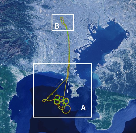
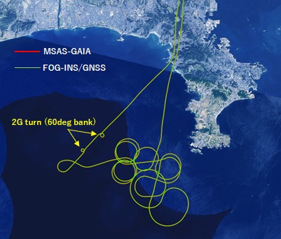
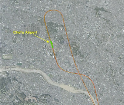
Mupal-α flight path, area A above Sagami Bay and area B around Chofu Airport.
Navigation data of our FOG-INS/GNSS and the MSAS-GAIA are shown in green and red respectively.
(Map source: National seamless aerial photo map of Geospatial Information Authority of Japan)
Click to enlarge image.
FOG-INS/GNSS specifications:
| Measurement range | Angular rates of three axes: ±180 deg/s Acceleration rates of three axes: ±98 m/s2 (±10 G) |
|---|---|
| Attitude (roll & pitch) error | 0.1 deg (rms) |
| Heading (yaw) drift | 1.0 deg/h (0.0003 deg/s) (rms) |
| Speed | 0.1 m/s (rms) |
| Position | 3.0 m (rms) |
| Power supply | ±15 V, +5 V |
| Output form | Digital output (RS-422) |
| Dimensions | 144 mm (W) × 144 mm (D) × 80 mm (H) |
| Weight | 1.8 kg |
| Temperature range in operation | -20 °C to +60 °C |
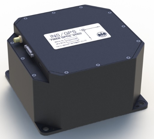
FOG-INS/GNSS